Showing posts with label Arduino. Show all posts

All The Miscellaneous Things


A so-called "American Football". Photo by Dave Adamson (link)


College Football Update

J and I go to games at Michigan Stadium to see the Wolverines play football. We've had season tickets since 1995, although we haven't been at all of the home games. 

It's not a stadium known for its high noise levels. From my experience, the loudest crowd reactions are:
  1. The end of the James Earl Jones movie that is shown right before the team runs onto the field
  2. When the announcer introduces the Veteran of the Game, usually a Word War II veteran, during a TV timeout
  3. When the dog catches the frisbee

The crowd also cheers loudly sometimes when the team makes a good play. 

Really? More boats? 

Following my inexplicable obsession with cool watercraft: 
  • This houseboat/camper boat is actually something I would consider owning if I lived near water.  Although if I lived near water, why would I need a camper for the water. I could just go home. I need to think this through more...
  • This "yacht" jet ski, whose design is intended to reflect that of larger boats made by the same manufacturer, is also something I would definitely own.  

Random Stuff

Books
Looking for something new or different to read? The "Recommend Me a Book" site shows you the first few pages of a book so you can check it out and see if it's interesting. If you like it, you can find out what book it's from. If you don't like it, you can click "Next" and see the first pages from another book. 


Arch Design
This is a fun and easy-to-follow video that shows how arches are designed, and how to use a chain to easily discover whether an arch you've designed will stand on its own. 
Don vs. Electronics: This Time It's Personal (and Educational)

---

I've been working on putting together a soldered version of the elevator project I recently completed (to my own satisfaction, that is) using breadboards.

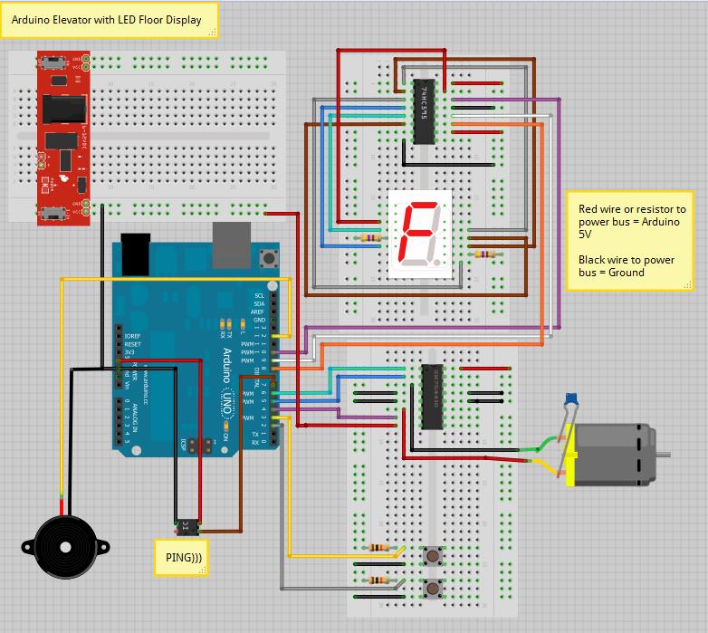
I spent quite a while drawing the circuit, resulting in the following diagram. I used the Fritzing program to draw this. It gives you a blank circuit area to work with, and you can put breadboards into the drawing space and wire your components together.


From there, I drew up a circuit diagram on graph paper, and tried to identify the inputs, outputs, and location of the chips. I wanted to have some ribbon cables connecting the Arduino to the circuit board.

Unfortunately, I didn't lay things out very well - I had one of the ribbons going to two different places, and the connectors I bought don't "stick" into the ports on the Arduino - they just fall out. I'll have to do some more investigation into the right kind of connectors before I can continue.

Here are a few pictures of the board - it's super ugly, but these things often are. It's the first one I've done from scratch, so I may be able to improve on it if I go another round with the soldering iron.


Some notes - the circuit diagram and a mock layout on graph paper. The mock layout looked good on paper, as they say, but it didn't work out when I was ready to connect the ribbon cables to the board. Oops!


The beginnings of the board. I have soldered a few components in place, and am in the process of drilling the holes for the buttons.


Same as before, but with the ribbon cables that I want to use to connect the board to the Arduino and power supplies.


The front of the board, with the chips in their sockets and the wires snaking around however I could make them fit. Presumably, there would be a cover over this board so you could only see the buttons and LED display, although on further inspection, most of the other components, and some wires, were almost as tall as those components.


The back of the board, where the ugly happens. The red wire is the positive "bus", and you'll note a few places the insulation was scraped off the wire so I could hook a component directly to it. This, and many other tricks I tried, were found on the internet by other people who can do this and make it look pretty. The black wire, and the associated blobs of solder that form solid lines, is the ground "bus". There are quite a few places in the wiring where components are wired to one or both of the positive/negative buses that I felt it was necessary to run those wires all over the place. The bottoms of the buttons, and some of the chip connections to the buses, were made with leads clipped off of spare components.

I've learned a ton from this experience. My first diagram had the wires on the right side of the LED display one space lower than they should have been, and I had all but the final wire soldered before I realized it. Lots of lessons learned, and my soldering skills are better now, too.

Now - back to researching circuits some more, and then to find some better header connectors to replace the ones I bought. Eventually, I'd like to make one of these:


I don't actually want to make one of these. Just kidding. Dad, recognize this?

---

Elevator Upgrade: A Man's Work is Never Done


I was talking to a friend at work about how enhancements to the elevator project could go on and on forever - different gears/pulleys/motors, fitting it into a dollhouse, using microswitches or other sensors to detect floors, platforms and/or ladders for college students to use when they break into the elevator shaft, and so on.

And it occurred to me: this elevator is missing something important. Sound!


If the sound you were thinking of was elevator music, yes, it is also missing that. That will be part of Version 2.0, along with a tiny phone you can use in case of an emergency.

Arduino Elevator Update: Now Accepting Lego Passengers


Here's a video of K running the elevator. Co-starring a lego man and his faithful dog.


Some of the parts are described in this previous post, although parts have been moved around and added.

I added two buttons, helpfully labeled "Up" and "Down", to control the direction, and a 7-segment LED display to show the current "floor".

As you can see, the elevator's construction has roughly the same quality as my video-taking skills. But that's OK - putting together a more attractive elevator and control panel will be an enjoyable step after getting the code and wiring all correct.

Elevator Circuit using Arduino


This is a diagram of the elevator circuit. So far, it's not working, but I am trying to find some help online to see what I can do to solve the problem.


The Elevator is Uplifting

---
Elevator "Up" Date


The elevator mechanicals - RIP old drawer hardware...

I've been working on the mechanical part of the elevator project lately, and I thought I had an easy idea - use some of the drawer runners, the ones that have the little wheels that the rails ride on.

I figured I'd just use one rail for a guide, and two of the little wheels to attach to the elevator car.

That didn't work because of the way the rails are constructed - they are only shaped to cradle the wheel on one side, and are flat on the other. That means putting the wheels into the rail vertically would cause the car to flop out of the flat, open side.

I put up two rails next to each other, with the curved (closed) sides on the outside, and that was enough to keep the wheels from flopping out. I superglued some of the drawer rail parts together well enough so they would slide without much friction. I then glued some other wood pieces to it to create a test platform. It's pretty ugly to look at from the back, but it works, and it is enough of what I would call a "Proof of Concept" to be happy with it.

The next challenge was to get the motor working with the rest of the circuit. For all of my testing of the ultrasonic sensor (the one that tells the program how far the nearest object is) I used a tiny toy motor. It doesn't take much power to run that tiny motor, but the bigger motor I am using to raise and lower the elevator car drains a lot more of the power from the rest of the circuit. As I was setting everything up, I noticed that the ultrasonic sensor was not working at all if I hooked up the bigger motor. I went back to my book, "Arduino Cookbook" and checked the wiring diagram again. I knew I needed a second power source for the motor, and I had one setup for that, but I discovered that I hadn't hooked it up correctly. The diagram got me straightened out.

I set the program to raise the elevator car until it was about 3.5 inches from the sensor and hooked up the really fancy pulley system to give the elevator its final test.

The Moment of Truth


A Few Pictures


The setup at the bottom of the rails is the sensor and the power supply for the motor. The sensor is the two small metal cylinders - one sends out a signal, and the other receives it as it bounces back. The time between the "sent" and "received" times can be converted to a distance by the program.

The red light is part of the power supply for the motor, and the black cord coming out of it is plugged into a power strip that's not pictured.


At the top of the elevator rail is the Arduino Uno board (the blue one) and a breadboard that contains a chip called an H-Bridge. It's the H-Bridge's job to control the motor based on the Arduino's commands, turning it on and off, and setting its speed and direction.
You can see the string wound onto a threaded rod, attached to the motor. This raises and lowers the elevator.


M helped me measure the distance between the sensor and the bottom of the elevator car. About 3.5" which is what I was hoping for.

I still have some work to do - it's not an elevator if you can't get the car back to the first floor! Next up, I'll add some buttons to the circuit to allow a user to control its up and down motion. That will require some changes to the program to handle the button presses, and to know where the car is. I don't want the car to keep going up if it's already at the top, and there's no need to let it back down if it's already at the bottom.

I'm also going to create a better rail system than what I have. It works, but is not a very elegant solution, and everyone knows that if there's one word that describes me, it's "elegant." (Maybe not.)

---


An updated shot of some of the components - the ultrasonic sensor is now soldered to a small circuit board instead of plugged into a breadboard. The wiring is more complete and it's been tested. Some of my later posts in this blog have a link to YouTube videos of it in action.

Elevator: Screw Drive, or Not?


Elevator with Screw Drive

Proof of concept of using a screw-driven elevator. It works, but it may not be the right solution.

The first garage door opener we had at this house had a long threaded rod that turned when the door opener was activated. The door was hooked to the threads and as the rod turned, it moved the door up or down by pulling the connector down the threads. I thought for the elevator I'm working on that I should borrow from that idea. I attached a threaded rod to the shaft of the motor, and glued some nuts to the elevator car. My hope is that using a screw drive will help me avoid something more complicated, like using pulleys and counterweights or some other complex system. And as a bonus, all the parts are easily found at the local hardware store.

I bought some 1/4" rod with 20 threads per inch, and a half-dozen nuts. I put the nuts on the rod first, then glued them to a small piece of wood. I glued a few more nuts to help square up the wood as it moved on the rod - otherwise, it might have twisted sideways and not run smoothly.

The good news is that it works; the motor runs, turns the rod, and the test "car" moves up or down depending on the direction of the motor.

The bad news? Just as the garage door opener produced a horrible amount of vibration when it ran, this setup also produces quite a bit of vibration. Without anchoring the end of the rod to something, it vibrates plenty, which is not good for the motor. And if the rod doesn't line up pretty well with the motor's shaft, it makes the motor work too hard.

I might be able to solve the vibration problem by using a rod with fewer threads per inch. This would allow the motor to run more slowly, and would reduce the vibrations. It's not easy to find threaded rods with (say) 16 TPI at the hardware store, so I might have to see if I can make one. I think I'll have to make the rod's diameter bigger, though, to get that low number of TPI. I have a few dies that have 10 or 12 TPI, but they're 7/16" or 1/2" diameter.

As much as I'd like to go with the screw drive, I am starting to think it's not going to be a practical approach, and I'm going to spend some time looking into pulleys and chain systems.

Speaking of pulleys and chains, this place is fun to look at. They have a huge catalog which also shows how to calculate various setups for chains, pulleys, etc. You can download the catalog as a PDF, but it's pretty big.

Made In Brooklyn
I like these videos by Dustin Cohen about people who make things (jewelry, violins, and watches) in Brooklyn, NY. There are only three right now, but I hope there will be more soon.

Yes, Someone Does Work Here


Wow - the guy who runs this place has been invisible lately. Maybe some pictures and various news tidbits will help get him back on track.

In the past few weeks, we've been pretty busy - the elementary school's Ice Cream Social, some trips to the pool, M's school tennis match, several floor naps, and a quest into the world of electric motors (torque vs. speed). Here are a few pictures to sum up some of our activities:


K is living the good life at the pool (Not shown: the haircut he got shortly after.)


The boys and their piano teacher, Mrs. Waller, at their annual recital. All of the students did a great job - I'm always impressed.


K pursues the ball at his last soccer game of the season.


M playing tennis for Slauson's Sixth Grade tennis team. He's the top-left player. They played their matches against the other Ann Arbor sixth-grade teams at the U of M tennis facility, which was gorgeous.


Our new Yamaha piano, complete with a lot of music. All of us have been playing lately. It even makes me sound good.


In search of a motor for the elevator project, I decided to go with a configurable gearbox whose speed and torque can be adjusted by adding or removing sets of gears. It was harder to put together than I thought it would be, although my Japanese language skills have improved. (Actually, there are enough English instructions inside that I finally got it working.)

A Few Other Notes
Today we went to the Food Gatherers "Grillin'" picnic. We've been going for quite a few years now, and always enjoy the food and entertainment.

The kids and J have one more week of school and work, respectively. My work continues and continues without end, regardless of season, so I hope the three of them appreciate their time to do some new things, and will allow me to live vicariously through them.